


Fire System Design
Our Services
BROCHURE.DOC
Download our document to see specific data of the service and how we work.
Fire System Design
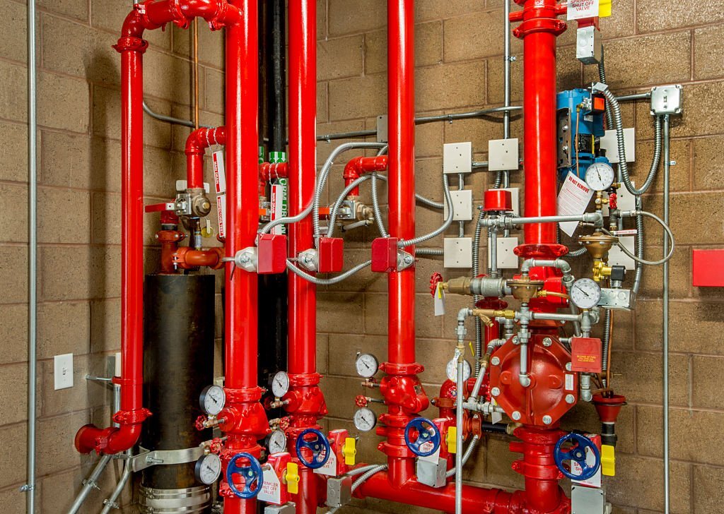
Fire Hydrant System
Fire Hydrant Systes
Fire Hydrant Protection System is designed to fight fire of huge proportions, in all classes of risks. It is designed to be in operation even if a part of the affected structure collapses. It consists of a system of pipe work connected directly to the water supply main to provide water to each and every hydrant outlet and is intended to provide water for the firemen to fight a fire.
At least one hydrant point shall be provided for every 60 m of external wall measurement in case of light hazard occupancy, for every 45 m in case of ordinary hazard occupancy and every 30 m of external wall measurement or perimeter of building/unit battery limit in case of high hazard occupancy.
The hydrant system shall be hydraulically so designed that when half of the aggregate pumping capacity is being discharged at the farthest/hydraulically most remote point and the other half in the most vulnerable area en-route, a minimum running pressure of 5.25 kg/cm² is available at the former point and the rate of flow of water does not exceed 5 m/s anywhere in the system (flow through one hydrant can be taken as 600 litre/min for this purpose).
In the event of fire when any of the hydrant valve in the network is opened, the resultant fall in header pressure shall start the AC motor driven fire pump through pressure switches automatically.
Fire Sprinkler System
Fire Sprinkler Systems are a Life Saving System and are designed to protect the building. Data says 96% of buildings that had fires and were completely protected by fire sprinkler systems were controlled by the fire sprinklers alone.
K-factor helps to calculate the discharge rate from fire sprinkler heads. It’s calculated in imperial units for the United States by using the flow in gallons per minute (gpm) and the pressure in PSI Metric.
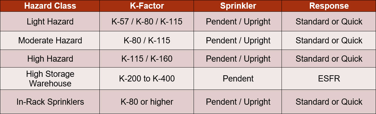
In fire protection engineering, the K-factor is used to calculate the discharge rate from a Sprinkler Nozzle.
Medium Velocity Water Spray System (MVWSS)
The density of water application on the surface to be protected shall depend upon the type of flammable liquids handled in the plants and also upon the object of protection and site conditions.
Nozzles are generally used for spray angles between 60° and 140°. They are recommended for usage in various applications with different K-factors between 18 and 100. These nozzles are used in the protection of high hazard plant areas, horizontal tanks like bullets, spheres, vertical atmospheric fixed and floating roof type tanks, conveyors, cable cellars and similar applications.
The spacing of detectors in rings shall not be at more than 3 m when measured along the curved surface of the vessel. For conical roof the detector shall be installed on 9 m2 area basis. The detectors shall be located at not more than 1 m from the shell.
High Velocity Water Spray System (HVWSS)
High velocity water spray systems are installed to extinguish fires involving liquids with flash points of 65°C (150°F) or higher. Three principles of extinguishment are employed in the system, namely, emulsification, cooling and smothering. The result of applying these principles is to extinguish the fire within a few seconds. Equipment like Transformers, oil filled equipment of power stations, Turbo-alternators and Oil-fired boiler rooms and oil quenching tanks are generally extinguished with the help of High Velocity Water Spray System.
For control mode, water shall be applied at a rate of not less than 10.2 lpm/m² of the surface area of the entire transformer including the bottom surface, radiators, conservators, etc.
Nozzles are generally used for spray angles between 65° and 150°. They are recommended for usage in applications with different K-factors between 18 and 110. These nozzles are generally used for oil filled equipment like transformers and other types of oil tanks.
Automatic detection equipment shall be so located and adjusted as to operate reliably. The location of detectors shall be based on several factors, such as nature of hazard, air velocity, temperature variations, etc. For transformers the detectors shall be as close to the shell as possible at all places subject to electrical clearance.
Fire Extinguisher System
Fire extinguishers should be provided both for protecting building structure as well as occupancy hazard contained therein. Generally, fire extinguishers should be placed as near as possible to exits or stair lands without hindering the escape routes.
Size determination shall be on the basis of the specific combustible metal, its physical particle size, area to be covered, and recommendations by the fire extinguishers manufacturer on data from control tests conducted.
Extinguishers should be sited in such a way that the user may not have to travel more than 15 m from the site of the fire to reach the extinguishers. Wherever possible, advantage should be taken of normal routes of escape by placing these in positions where these shall readily be seen by persons following the natural impulse to get out of danger.
The types of extinguishers mentioned below against each class of fire are generally most suited.
a) Class A fires — Water, foam, ABC dry power and halocarbons extinguishers.
b) Class B fires — Foam, dry powder, clean agent and carbon dioxide extinguishers.
c) Class C fires — Dry powder, clean agent and carbon dioxide extinguishers.
d) Class D fires — Extinguishers with special dry powder for metal fires.
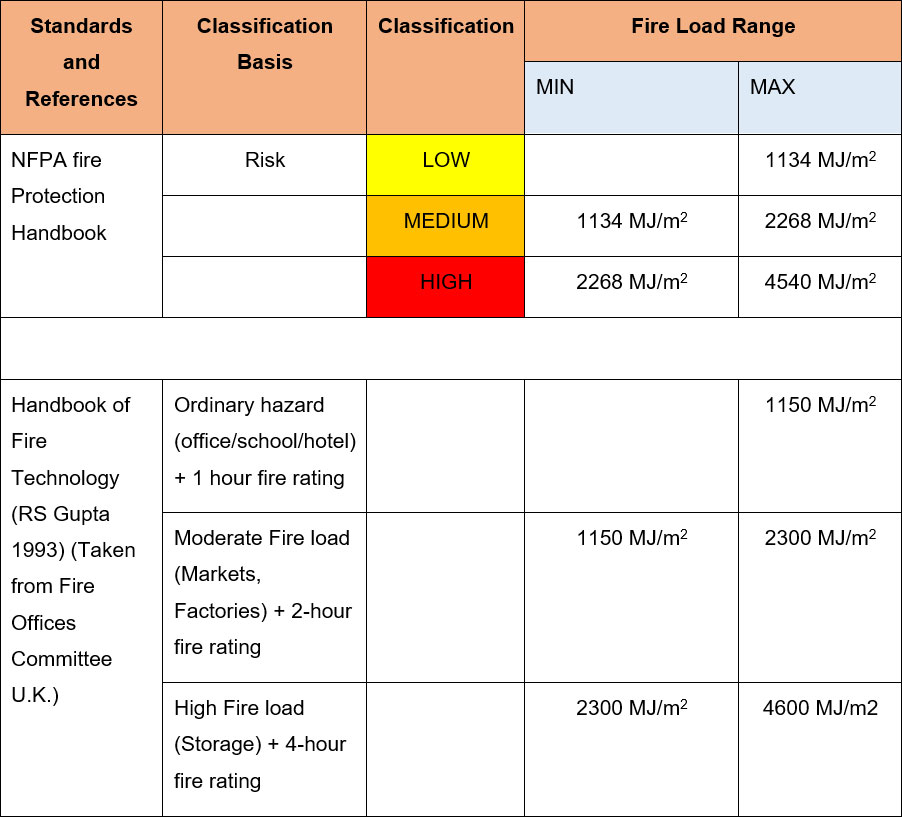
Fire Load Calculations
Fire load is the total energy content of all the combustible materials stored in a building or space. It shall consider furnishing, contents and combustible building elements expressed in Mega Joules. Fire load density is the energy content per unit area expressed in (MJ/m2).
Fire load calculation is a study that calculate the total energy content in a building and provide an insight into the fire risk a building possess. It is a quantitative study to determine fire rating of the building depending on its combustible contents.
Objective
The fire load study of the premises is performed to determine fire load and fire load density that should be used as the basis for the evaluation and design of the structural fire performance of the building. Fire load calculation provide information regarding areas of high concern and provide view with regards to fire grading of the facility. Fire load study helps to determine the hazard category of the facility in case of a fire and provide adequate data for fire protection of the premises. Fire load study decides the basis of industrial classification as per the standards. Fire load study determines the design basis for sprinkler systems, fire alarm system and fire extinguishers requirements. It is essential for industries with highly combustible material to conduct fire load study to evaluate the extrapolation of risk.
As per NBC 2016 Chapter 4 Annex A calorific values of common materials are given for calculations.
Why Building owners should consider fire load calculation
Methodology
- Statistical distribution of fire loads in buildings
- Fire initiation frequency
- Effectiveness and reliability of the fire protection features that contribute to fire control in the early stages of the fire
Determining fire loads in a building requires measuring the mass of all the different types of combustibles and their calorific values. The mass of an item in a compartment can be
determined by weighing it (weighing technique) or by determining its volume and identifying its density (inventory technique). The direct-weighing method should be used for items that can easily be weighed, such as toys and books; the inventory method may be used for heavy items that cannot be weighed, such as heavy furniture and built-in shelves. In most cases, a combination of the weighing and inventory methods is used, in which some common items could be pre-weighed, and then the surveyor notes their inventory.
Benefits
- Distribution of concentrated fire loads to reduce fire load density.
- Fire rating requirements for compartmentation to prevent spread of fire during the entire duration of a fire incident.
- Gives insight for the substitution of combustible materials with materials whose calorific values are less. For example, corrugated plastics boxes and polyurethanes pallets can be replaced with carton corrugated boxes and wooden pallets.
- Helpful in determining the K-factor for the sprinkler system and evaluation of exiting sprinkler system as per the occupancy and storage.
- Essential document for fire system design report preparation.